
Introduction
Since 1958, stereo recordings have been released on vinyl records, to be played either through mono-only setups, which are now quite obsolete, or through stereo cartridges connected to stereo amplification and loudspeaker systems. As a result of the clever way in which stereo is recorded into the groove walls of vinyl releases, there is no reason why a stereo recording cannot be played through a mono set up, or a mono recording played through a stereo one. There are, however, great benefits in terms of sound quality, especially with mono recordings of an older vintage, to be had by playing mono vinyl releases through a pre-amplifier system that sums the two stereo channels together to produce a purely monaural output. As a consequence of this, many systems, particularly more serious ones, from the first age of vinyl (from roughly 1950 to 1985) were equipped with a panel switch that the user could operate when playing mono releases so as to reduce surface noise, distortion, and rumble across the two stereo channels. The mono switch could also be operated to bring the same improvements to heavily worn or damaged stereo recordings, trading the distressing effects of high surface noise and distortion against the illusion of stereo for what would hopefully be a better listening experience.
At the time of writing, the second age of vinyl (from about 2010 onwards) is very well under way and sales of vinyl records have actually exceeded those of CDs for the past two years. Many new phono-stages have been put onto the market, with a great many features that were most often absent from those of the first age of vinyl, the two most often seen being variable gain and variable load impedances. The latter feature is a little more questionable than the former, bearing in mind that all MM cartridges are designed to work with a load impedance of 47kΩ (although using 50kΩ with shorter leads of lower capacitance does bring about some improvement to frequency response). One feature that is conspicuously absent in this new age is the faithful old mono switch, which appeared on all but the very cheapest of stereo equipment from the late 1960s to the demise of vinyl as the predominant medium of high quality music consumption with the advent of the CD and later digital audio formats.

Figure 1. Cover of a 10" mono LP
Although there are not many mono releases being issued today, there are a plethora of earlier mono releases such as the 10 inch LP of Figure 1 that will give a much more satisfying result when played in true mono mode today. The very poor vertical compliance of early pick-ups designed to play mono pressings would also create a vertical wear pattern that in can generate some very distracting cross-channel distortion artefacts when played back using a stereo set-up. It is the opinion of the author that some control that allows summing to mono is absolutely indispensable when playing back these earlier discs. At the time of their cutting, not very much thought was given to their compatibility with the stereo system that eventually superseded them some years later, and although the stereo system for records, like the stereo system for FM broadcasting, was designed for backward compatibility (unfortunately there is no 'pilot tone' on stereo records to allow for automatic summing), there is no doubt that there are significant disadvantages to this simplified approach.
Stereo groove geometry
To understand the improvements that channel summing can bring about on mono or damaged pressings, it is first a good idea to take a brief look at how exactly a stereo signal is recorded into a single groove. Most readers will already be aware of how this is done, but there are some important points to consider, particularly that not all planes of motion are created equally in terms of their usefulness to high quality audio reproduction.
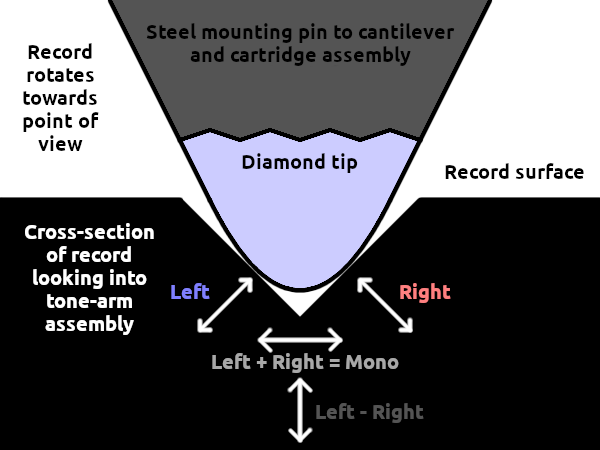
Figure 2. The groove geometry of stereo encoding
The general principle is demonstrated in Figure 2; a rendition drawn up by the author, but certainly found in many other forms elsewhere on the internet. Looking into the tone-arm from across the record, the left groove wall moves diagonally upwards and to the left to induce a positive signal into the cartridge assembly, while the right groove wall moves diagonally also, to the right and downwards to imply a positive signal in the right channel. As a result, if an identical signal is encoded with in both channels at equal amplitude, the up and won motions cancel out and the stylus only moves only in the lateral plane; to the right for a positive signal and to the left for negative. Consequently, a signal that exists equally and oppositely on both channels results in a purely up-and-down motion of the stylus.
A mono record - aside from some very early or rather esoteric recordings that used a vertical modulation known at the time as 'hill and dale' - uses only the lateral side-to-side range of motion to record the signal. A mono cartridge likewise is, when set up correctly, only sensitive to stylus motion in the lateral plane. It is therefore possible to play mono records on stereo set-ups; where the left and right channels will be equally sensitive to movement in the lateral plane, and stereo discs on mono set-up; where the lateral plane of the cartridge's sensitivity resolves to sum the left and right groove wall together laterally while being insensitive to the difference between the two channels which exists in the vertical plane. This sounds all very well and good, and for the most part it certainly is; manufacturers found a very elegant way in which to introduce stereo records and players while maintaining backward-compatibility. Earlier stereo systems such as those pioneered by British engineer Alan Blumlein, inventor of the moving-coil cutter-head, encoded one channel in the lateral plane and the other in the vertical plane; a working system that unfortunately suffered from audibly different recording characteristics of each channel due to problems with linearity, maximum level and noise the vertical plane that very still exist today.
While the lateral plane of operation yields comparatively good fidelity, with a recording characteristic that usually allows for a decent amount of bass energy and stylus acceleration that match the spectral distribution of recorded music, the vertical plane rather lacking. First of all, the overall linearity is decidedly poorer as the vertical tracking of the stylus relies solely on the compliance of the cartridge to push the stylus down into the groove as it recedes from a ‘hill’ into a ‘dale’, rather than having an opposing groove wall to the side to push it in the right direction. In consequence of this unbalanced operation, it is very possible for the stylus to lose contact with the groove if the acceleration of the groove into the record exceeds the ability of the cartridge compliance to accelerate the stylus into the groove, promising very audible distortion. The linearity is also degraded by the fact that vertical tracking angle is rather variable and very difficult to adjust compared to horizontal tracking - or azimuth - in not only most set-ups where it is highly dependent on the tracking force as well as tone-arm angle, but also when the master lacquer of the pressing itself when it was cut, varying between 15° and 25°, which is not a tolerance particularly prescriptive of the sort of linearity required for high quality sound reproduction. In addition to limits on acceleration, the vertical plane suffers also from much greater restrictions on excursion than the lateral plane; the excursion cannot exceed the height of the groove, or the groove will simply not exist anymore. This lack of available excursion precludes the recording of any appreciable amount of bass energy vertically; in fact mastering engineers have to be very careful to pan bass instruments to the centre or use a low frequency cross feed filter to prevent any unbalanced bass notes from throwing the cutter head up and off the lacquer.
Low frequency noise, originating either from the cutting lathe, the platter bearings of the playback equipment, and even imperfections in the surface of the record itself (which contribute a great deal more noise than most aficionados would like to believe, regardless of how warped the disc appears to the eye), manifests itself more apparently in the vertical plane than the lateral plane. The noise is noticeably greater in the 20-200Hz range in the vertical plane, outside the remit of a conventional ‘rumble filter’, which should really be called a ‘subsonic filter’ as it removes the inevitable malevolent energy outside of the audio band that would otherwise cause most loudspeakers and headphones to generate heavy intermodulation distortion. Below 20Hz, the difference in output on a competent system appears to be almost the same in the vertical and lateral plane.
By viewing the stereo recording system as a lateral summing and vertical subtraction of the two channels, rather than left and right at 45° from lateral and perpendicular to each other, it becomes apparent that this is a very useful arrangement indeed as far as recording real world audio is concerned. With normal programme material, the relative level of the difference between left and right is much less than that of their sum which means that the amount of distortion generated vertically in the difference between the two channels will be kept to an acceptably low level. Very little energy is required in the difference between left and right to present the listener with the illusion of stereo, and human hearing is quite insensitive to direction at frequencies below 300Hz, so there is no need to record any excursion inducing bass vertically. Distortion increases exponentially with increased recording level, so care has been taken since the beginning of stereo mastering to keep the vertical excursion as low as possible when mastering discs, often applying dynamics processing to the sum and difference separately, with heavy limiting and a steep high pass filter applied to the difference channel, as opposed to left and right. While distortion cannot be induced laterally by vertical excursion of the stylus in the groove, it is quite possible for lateral excursion to cause non-linear artefacts in the vertical plane. This most often happens when the groove accelerates the stylus very quickly in one direction activating a distortion mechanism known as ‘pinch-effect’ where the groove pushes the stylus upwards while accelerating laterally, resulting in a form distortion that manifests itself in the difference between the two channels; a very good reason for using a mono switch when replaying mono records.
Surface noise
While surface noise is quite inevitable in a system that revolves around dragging a microscopic diamond through a microscopic ditch pressed into the surface of an imperfect plastic disc by a metal stamper, moulded around a metal former that was in its turn, moulded from an acetate disc cut on a mechanical turntable by what is, essentially a tiny knife mounted on a pair of coils, it is usually quite possible to obtain a signal to noise ratio that most musical material can be pressed into to a satisfactory degree. SNR of a stereo disc is usually in the region of around 50-70dB, with the upper estimate being rather optimistic in the opinion of the author who has not been fortunate enough to observe quite this much dynamic range in the real world. Direct metal mastered discs were rumoured to be able to reach this lofty height, and although the author has some very good examples in his possession, transfers made from these discs do not seem to exceed more than 68dB. This figure was helped along by some very generous first order high pass filtering to preclude any turntable rumble below 200Hz from skewing the noise floor upwards, alongside the benefit-of-doubt that the recorded peak level is not past the point of audible distortion, the author not being inclined towards subjective assessment without the original source at hand for a fair comparison.
Each groove wall, and therefore each channel can be assumed to be a separate and uncorrelated source of noise for the purposes of assessing surface noise, and by summing the left and right channels to mono there will be a partial cancellation of the noise while the mono audio signal will be retained at full level. Theory dictates that a 3dB reduction of surface noise will be brought about by switching to mono in such a manner; a quite audible improvement. In reality, things are even better, as the already lambasted vertical plane will contain much more low frequency noise than the lateral. As will be shown (and also heard) below, as much as 6dB or more of noise reduction may be obtained by switching to mono.
Sample 1A. Left channel of lead in noise
Sample 1B. Mono sum of lead in noise
Sample 1C. Full stereo of lead in noise
Sample 1D. Vertical difference of lead in noise
Sample 1 contains 4 renderings of the same 6 seconds of lead-in noise from a relatively unscathed mono LP issued in the early 1960s. The level has been brought up almost 40dB above the peak recorded level so as to make the noise floor clearly audible. Pre-echo is quite clearly heard in the last couple of seconds of the sample in addition to the sound of the master tape coming to the end of its non magnetic (and thus much less noisy) leader in the last second, causing the amount of audible hiss to rise abruptly. This clue in the last second of audio (before the programme material itself begins) is a useful indicator that tape noise, which will be identically correlated from the mono master tape in both left and right channels, is not going to skew any noise measurements against the benefits of mono switching when summing both channels. To help things along further a 20Hz 4th order Butterworth high pass filter has been applied to the samples (a matter of course for the author when making transfers from vinyl records) so as to prevent subsonic disturbances from swamping any useful noise measurement - as will be the case for all samples to follow. All the parts of this sample were rendered from the same transfer with the channel summing, splitting, and subtracting applied digitally in Audacity. To hear the full effect of the differences between each rendering it is highly recommended that high quality headphones are used in a quiet environment; all the samples are high quality FLAC files sampled at 48kHz.
Sample 1A contains only the left channel in isolation, presented as mono; a much better comparison than full stereo to explore the effects of channel summing without the spatially distracting presence of cross-channel noise. Impulse noise, in the form of the usual clicks and pops along with less granular 'rustling' is easily audible, as it will be for any disc of this age with the noise floor brought up to an average level of some -21.8dBFS. It is easy to hear that most of the noise is below 500Hz, which is inevitable for any set-up, and that this lower frequency noise is ever so slightly uneven, changing its intensity and spectrographic character perceptibly every revolution of the the disc. While some of this noise originates from the turntable itself - a very competent Technics SL-1200 - it predominantly emanates from mostly vertical imperfections in the surface of the record which occur almost universally in all pressings. Happily, the noise starts to rise just as our perception of sound intensity diminishes with the lowering of frequency, and the overall effect is quite tolerable in practice. Here, however, the unwelcome contribution of this uneven low frequency noise is readily noticeable, and some very careful listening will also reveal an ever so slight tone-arm resonance that manifests itself as a broad (and therefore well damped) peak between 600Hz and 700Hz, which is also innocuous in normal use.
Sample 1B renders the sum, or perhaps more accurately the average so as to avoid a doubling of programme level over Sample 1B, of left and right channels; what would be happening if the mono switch on a suitable pre-amplifier were to be engaged. Although the gain has been brought all the way up to the same level as 1B, the average level, and hence noise floor now sits at a much-improved -27.9dB; a very substantial reduction of 6.1dB! Subjectively, the noise is more stable, with much less intrusive rumble and remains fairly constant with less 'wind noise' for want of a better word. The sound of the master tape leader ending, along with the pre-echo is also more easily audible, a sure sign that the dynamic range of the disc has improved as a result. Impulse noise in the form of clicks and pops, sitting slightly above the constant noise floor, that are fairly constant even on older discs of a better condition such as this one are also reduced in their intensity, as the physical anomalies that cause them tend not to occur in each side of the groove wall simultaneously. Thus, while the frequency of these small annoyances increases, their level decreased by a factor of two due to the averaging effect of summing to mono; they are much less intrusive subjectively as they begin to blend into the constant background noise, at least now being only half as loud.
Sample 1C presents the full stereo capture of the lead-in noise, with no processing other than the 20Hz 4th order high pass filter. Listening with headphones will quickly reveal the distracting spatial effect of uncorrelated noise on each channel which becomes increasing differential as frequency diminishes. The mostly low frequency noise that sits between each channel is not particularly pleasant to listen to at this magnified level, while impulse noise also takes on a spatial effect with individual clicks and pops rarely occupying the centre of the stereo image. Comparing Sample 1C to 1D with a pair of high quality headphones immediately reveals a great difference in the obtrusiveness of impulse noise and low frequency rumble. With a pair of stereo speakers in an ordinary listening room, the difference will perhaps not be quite as obvious, as some of the low frequency noise will cancel through acoustic mixing, but will audible; especially if it is further excited by a room response mode.
Finally, Sample 1D contains only the difference between the two channels and therefore the vertical element only, rendered as mono. Impulse noise is roughly at about the same level as it is in the lateral mono rendering of Sample 1B, but low frequency rumble is much higher, being far protruding far more into the upper bass region, hence the reason why 6dB of overall noise reduction is acquired through mono summing and not the expected 3dB if the noise was only randomly uncorrelated. Above 1kHz, the noise floor is roughly the same in Sample 1D as it is in Sample 1B, so all the extra cancelling noise is indeed in the bass region. Interestingly, the pre-echo in the last second or so of audio is still audible vertically, which implies that the surrounding deformation caused by the cutter-head as it passes close the groove during the next revolution of the lathe has a substantial vertical element to it. Vertical deformation might be expected to occur in a stereo pressing where the cutter-head moves vertically, but this is a mono disc, so the lacquer must be deforming possibly upwards and away from the groove as it is cut and not simply to the side.
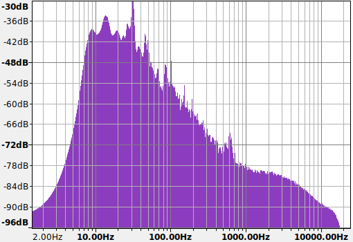
Figure 3. Spectrogram of Sample 1B
The spectrographic profile of the summed mono surface noise is shown in Figure 3, showing that the vast majority of the noise resides below 500Hz. From the left of the scale the noise floor rises up quickly as the subsonic filter passes the increasing frequency, with a peak of 14Hz rising almost higher than the highest peak at 30Hz - most probably rumble from the cutting lathe itself. The 14Hz peak is a normal feature on any turntable that uses a tone-arm and a cartridge, usually in the range of 7Hz to 14Hz, and is caused by the resonance of the cartridge compliance against the mass of the tone-arm. While it appears to be quite benign, it is important to keep in mind that the 24dB/octave subsonic filter is actually attenuating by over 12dB at the point the 14Hz peak occurs, demonstrating just how important a subsonic filter is in practice if excessive loudspeaker excursion and the unpleasant 'fluttery', or 'shimmering', amplitude intermodulation distortion that accompanies it is to be avoided.
From 30Hz onwards the noise amplitude steadily decreases at a rate of roughly 9dB/octave; an effect of the RIAA equalisation bringing the gain down by 6dB/octave as frequency increases and also various mechanical low-pass effects in both the playback turntable and the cutting lathe. The aforementioned tone-arm body resonance is also visible as a little hump in the response from 600Hz to 700Hz, although the level of the resonance is not greater than the noise floor an octave lower. Between 1kHz and 3kHz the noise floor is fairly flat, but it diminishes again rapidly after this last point as the RIAA curve’s second time constant at 2122Hz comes into play, falling off almost completely at 18kHz; the upper limit of the Stanton 500 cartridge which was selected by the author for its high tracking force for the purposes of the transfer, as source material of this era rarely exceeds a bandwidth of 16kHz.
Mono discs
So far, only the effects of surface noise have been demonstrated, so it is now time to add some wanted audio into the mix to show how mono summing can help to reduce distortion. As already mentioned, lateral movement of the stylus can cause distorted deflection of the stylus in the vertical plane. This most often happens when either a high level of stylus excursion or acceleration is required, and becomes progressively worse as the linear velocity of the groove decreases towards the centre of the record. Sample 2 exhibits exactly this effect in action, combining these three holy trinities of infelicity together to produce easily audible distortion, with lots of accelerating high frequency content, and a high recorded level on the last track of the side. Mastering engineers would take pains to ensure that the final track on a side would have be have a low level and not much high frequency energy, most often arranging the order of tracks so that the quieter ones were at the end of the sides. Sample 2 is presented in the same manner as Sample 1, containing the left, mono sum, full stereo, and vertical difference renderings as Sample 1, from the same mono LP.
Sample 2A. Left channel of mono LP
Sample 2B. Mono sum of mono LP
Sample 2C. Full stereo of mono LP
Sample 2D. Vertical difference of mono LP
Starting from Sample 2A, the left channel only, it should be quite clear that the heavy and loud high frequency content of the brass instruments is causing some considerable ‘tearing’ and ‘fizzing’ distortion, particularly around the hi-hat hits that create distortion artefacts that seem to break down into the lower portions of the audio spectrum. The same surface noise of Sample 1 is heard in the background of the quieter section with the clarinet playing, to give a good idea of how far below the recorded level the noise floor will typically be on these older pressings, although a good of this noise is probably acoustic noise present when the recording itself was made, along with the usual tape hiss. When listening at a reasonable level, the low frequency noise described earlier should be easily identifiable.
Mixing both left and right down to mono, Sample 2B sounds noticeably less distorted than 2A, but is by no means at all perfect and still audibly distorted by some of the louder notes from the brass section and the hi-hat. There is also a subtle reduction of surface noise in the quieter section, and the clarinet sounds a little less bright; a sign that the overall level of distortion is being lowered. While it does sound a little less bright overall compared to Sample 2B, it is most certainly much more listenable and the overall level of distortion is nowhere near as intrusive as it is on Sample 2A, which would have the author reaching to turn down the treble control to attempt to remove some of the added harshness of the distortion. Conversely, while some added distortion can make a recording appear brighter and edgier, it certainly is not high fidelity sound reproduction and if some extra treble is desired, it is far better to obtain it through equalisation than the introduction of non-linear harmonics, intermodulation products, and the inevitable loss of detail brought about by their masking of the original sound. It is certainly easier to hear the instrumentation going on behind the brass in Sample 2B than 2A.
Sample 2C, the full stereo capture, is even less listenable than Sample 2A when compared with Sample 2B. Not only does it feature the same unsettlingly elevated levels of distortion as Sample 2A, but now the distortion is spread across left and right and distracts the listener from the centre; made even more pronounce by the disc in question being a mono pressing where all the sound emanates from the spatial centre. The distortion causes the top end of the perceived centre of the sound to widen out as the level increases, which is not a particularly pleasant effect subjectively at all. The partially differential and uncorrelated surface noise during the quieter section also has a more intrusive effect in stereo. With stereo discs, this effect is much reduced as the programme material’s spatial character will hopefully be stronger than the spatial effect of the distortion - which should normally be much lower than in Sample 2 – and surface noise.
As before, the vertical difference is presented in Sample 2D, which contains only the distortion and surface noise; a very useful indicator of distortion on mono discs that would ideally have no vertical element at all. Distortion is heard throughout the sample, mostly in the high frequency range where it manifests itself as a tearing sound – not very musical at all. It is easy to hear how much is being contributed re-listening to the first three samples after hearing Sample 2D, as it gives the listener a good idea of what exactly to listen for. The hi-hat hits are especially disruptive. By switching to mono, all of this distortion and rumble cancels out, resulting in a much better listening experience. If a stereo disc with the same intolerable amount of distortion is encountered, then switching to mono can bring about a similar benefit to sound quality, although at the cost of stereophonic sound of course.
Wear and tear
Moving on to discs in considerably worse physical condition, switching to mono can provide a good deal of release from the same unpleasant artefacts detailed above. Trauma may be inflicted upon records by a number of means ranging from a worn stamper at the beginning of its life, to rough handling causing scratches, and being played with a heavy, low compliance cartridge, possibly with a worn, deformed, or chipped stylus; the last of these engendering a signature hiss, only appearing on one channel. Stereo discs played with mono piezoelectric ‘crystal’ cartridges with no vertical compliance would often suffer severe vertical deformation to the groove, but very often mono discs would also suffer by low compliance cartridges putting enough pressure on the sides of the groove to cause deformation at higher recorded levels.
Pinch-effect, pushing up on the stylus as the groove accelerates laterally, in tandem with the same lack of vertical compliance could occasion the stylus to dig down into the groove, particularly so if it was of the cheap conical type that low compliance cartridges once used, causing vertical deformation of the groove; a sort of inverted pinch-effect distortion permanently worn into the disc. The author suspects this is the cause of the worst distortion in Sample 3 below; a heavily worn mono 7 inch single sourced from a very boutique shipping container, tastefully set up to sell of items of next to no value, retrieved from the main heap of a Hampshire rubbish tip. The disc itself was issued in the heyday of low compliance, heavy tracking cartridges, to an audience who evidently did not hold preservation of their records as a top priority.
Sample 3A. Left channel of rock single
Sample 3B. Mono sum of rock single
Sample 3C. Full stereo of rock single
Sample 3D. Vertical difference of rock single
The left channel as mono, Sample 3A, exhibits clearly audible distortion with characteristic crackling break-up effect throughout the sample, as the level is fairly constant due to the application of heavy limiting during mastering; the goal being to make the disc sound as loud as possible in comparison to other discs played along side it. Although the disc showed signs of substantial physical scuffing, like a lot of 3 minute 7 inch singles it plays quite quietly, aside from the distortion. Short playing 7 inch singles were usually cut with deeper grooves, spaced further apart to maximise lateral excursion and hence loudness, so the scratches have to be quite deep indeed to reach down into the point of the groove at the point of stylus contact. It is difficult to hear scratches in the programme material in any case as the level at maximum throughout and the pinch-effect-wear distortion has a crackly sound that makes it harder to discern clicks and pops. It's quite impossible to ignore the 'tearing' and 'fizzing' distortion during the vocal chorus, and as-is the author would prefer to listen to it with some sort of high cut filter to at least take the hardest edge off it.
In Sample 3B we hear the desirable effect of switching to mono mode; both the crackling and tearing distortions are reduced, although still certainly perceptible - nothing is perfect. The improvement is especially pronounced after 20 seconds or so, as the the disc is quickly approaching the end of its playing time, getting closer to the label and starting to suffer from the ill-effects of reduced linear velocity. The most profound difference is found between Sample 3B and 3C, the latter being the full stereo version of this disc featuring the same heavy distortion which now splats all the way across the stereo image, creating the same distracting effect described in the earlier section to a much greater degree; it really is very nasty here. The crackling effect sitting across the stereo field, as opposed to the centre, further supports the theory that this is mostly distortion caused by pinch-effect force. The mono switch really becomes a magic wand here, with a little flick yielding a night-and-day difference.
Sample 3D renders the vertical element only, which as before might provide a reference context for some more informed listening for distortion if it wasn't already so obscenely apparent. With only distortion, there are still no clicks and pops to be heard in the background supporting the idea that the grooves on this disc were deep enough to prevent the scratches digging down to the contact point and creating impulse noise on playback. While there is some low frequency noise visible on a spectrogram rendering of this sample, it is hard to hear on account of the heavy distortion and much higher recorded level. The vast majority of 7 inch singles of this era were mastered in mono, despite stereophonic sound being quite prevalent for the purposes of reducing vertical wear with mono piezoelectric cartridges, and also for the purposes of maximising the recorded level by prioritising lateral excursion only. There was also the correct assumption that singles were more likely to be played back on cheap semi-portable 'record players' were stereo sound would not be required.
Moving into the domain of wear caused by mishandling, Sample 4 is put forward as an example of how mono summing can improve a bad situation. This disc is an early DECCA FFRR LP issued in 1952, well before the RIAA curve was introduced as a playback standard. These LPs were usually packaged with a very fine and rather finicky plastic inner sleeve that was not particularly easy to get back into the outer sleeve. Rather than having to deal with this affliction, many listeners ignored the text on the outer sleeve imploring them to keep the record in the inner sleeve and simply threw the inner sleeve away, placing the LP back into the relatively rough and abrasive card outer sleeve, causing dust to ingress into the grooves and the record to become scratched slightly every time it was removed and replaced. This LP had no inner sleeve and had visible light scuffing to the surface as well as some other moderate scratches that look like the kind inflicted by misplacing the record over the turntable spindle by a distance greater than the width of the label. Being an LP, the shallow grooves are more prone to damage as the scratching does not have to reach down very low in the groove to dig into the stylus contact point.
Sample 4A. Mono sum of scuffed LP
Sample 4B. Full stereo of scuffed LP
Sample 4 contains over a minute of audio to get the listener fully acquainted with the source. Clicks, pops, surface hiss, and low frequency surface noise are all present. There is, however, no audible distortion, the disc being an LP with closely spaced grooves that would preclude the excessive excursion necessary to induce distortion, either through mis-tracking or wear. Vertical analysis confirms this, so there is no need to include either the left channel in isolation or the vertical difference here. Listening first to Sample 4A, the mono sum of both channels, the impulse noise is constant throughout, but not overly intrusive, although some scarring around the 45 second mark probably induced by scratching the disc with the spindle is a little distracting from the programme material. One of the lesser features of this recording is the wow and flutter, most likely present in the master tape itself as the disc was very carefully centred for minimal tone-arm swing prior to transfer.
Sample 4B presents with an increased level of surface noise, particularly in the low frequency range, much like in Sample 1, re-enforcing the idea that switching to mono can reliable reduce low frequency noise by a very considerable factor. The biggest difference, at least subjectively to the author, is that the clicks and pops are more distracting as they rarely appear in the centre of the stereo image, being either hard-left or hard-right, much like the distortion in the previous sample; pulling the listeners attention away from the centre of the image. The clicks and pops also appear louder as they are not averaged between channels, and the spatial dimension makes the temporal separation between them stand out more; they don't seem to fade into the quieter and more constant character of Sample 4A. This is exactly the same as the effect described in Sample 1, and Sample 4 is mainly included to show how these effects fit into the real-world when accompanied by undistorted programme material with a moderately high dynamic range. As the recorded level in the passage is quite low, switching to mono partially cancels the uncorrelated groove wall hiss, diminishing it by a noticeable level of 3dB and of course eliminating its spatial effect.
78RPM discs
A discussion of mono playback would be incomplete without touching upon the subject of 78RPM discs, the vast majority of which were issued before stereophonic sound was introduced, even afterwards were all mono releases without exception. Most discs recorded in the USA from about 1940 onwards, and many British discs from the early 1950s to the end of the era, will play back quite acceptably using the RIAA equalisation of a modern pre-amplifier which approximates most of the various recording curves from this era to within 3dB. Adding a suitable cartridge with an appropriate playback stylus to a turntable capable of reaching 78RPM means that it is easy to play these discs without investing too much money in esoteric electronics and other accessories. Many direct-drive turntables manufactured in 2021 now offer 78RPM as a matter of course, being easily integrated into the electronics of these decks, and the ability to quickly change out cartridge and stylus combinations by swapping head-shells allows very convenient realisation of a low cost system that play both shellac and vinyl.
The sound quality of 78RPM discs can likewise be rendered more palatable on a dual-purpose RIAA set-up by switching to mono and cancelling the vertical elements. In the UK at least, most 78s exhibit a characteristic background crackle that is thought to originate from granulation of the shellac itself around the particles of abrasive filler that make up the disc caused by the moisture and temperature cycling of the British climate and low quality shellac, bits of steel left in the groove from playing earlier discs with steel needles, or simply heavy scuffing. This noise has a very granular characteristic and is usually uncorrelated on each side of the groove wall, so averaging the two groove wall reduces not only the level of the noise, but also its granularity. Similar problems with distortion can occur on these discs, and although those from the later 1950s era usually have low distortion as a consequence of lighter pick-ups and the very hard shellac playing surface, many earlier discs have a great deal of wear distortion brought about by playing with heavy pick-ups and steel needles.
Sample 5 contains the first 30 seconds of a British 78 from 1954 issued on the DECCA FFRR label; aside from the inevitable surface noise a very good example with a response extending all the way up to 14kHz. A good 3 seconds of lead-in noise is included at the beginning of the sample. Having not been played with steel needles, there is little distortion throughout, but the higher recorded level of these later discs does create a little bit of fuzz during a couple of vocal peaks. Because the linear velocity is higher for 78s, low frequency rumble due to disc imperfections is brought up higher into the audio spectrum and is therefore more audible, despite the higher recorded level of the coarse-groove media.
Sample 5A. Left channel of 78RPM disc
Sample 5B. Mono sum of 78RPM disc
Sample 5C. Full stereo of 78RPM disc
Sample 5D. Vertical difference of 78RPM disc
In Sample 5A, we hear only the left channel which exhibits a moderate level of crackle and impulse noise with a rather grainy character which sticks out just above the music to the authors ears. Lathe and disc imperfection rumble is easy to hear with a pair of good headphones during the first 3 seconds before the song starts, but stays in the background with the recorded audio present. Underneath the crackle of the disc some background hiss is also apparent, but the crackle is more intrusive than this more benign noise. Slight distortion can be heard around 22 seconds due to the peaky waveform of the vocal part placing heavy demand on tracking of the stylus and also the cutter-head during mastering. Switching to mono mode in Sample 5B brings forward an expected improvement to sound quality with the rumble at the beginning of the sample moving out of the more noticeable 50Hz-250Hz range and down into the lower regions of the bass where the ear is less sensitive, although attentive listening can still pick it out. Wideband noise is reduced by a detectable 3dB, and the crackle is more benign to listen to with groove wall averaging taking place; now merging better with the background hiss and with the individual tiny clicks occurring at half the amplitude and twice the frequency is perceptibly less grainy. While the intro sounds ever so slightly cleaner, the distortion during the vocal peaks appears to be unchanged.
Comparing Sample 5B to 5C, the stereo capture, will give the best impression as to why 78s should be rendered as mono. The crackle is independent on the left and right channels which is distracting in the same way clicks and pops have been shown to be on LPs, with the rumble at the beginning of the sample throbbing across the two channels disconcertingly. During the vocal peak at 22 seconds cross-channel break-up is apparent, and the right channel suffers from distortion more than the left channel does, explaining why the distortion appears to be much the same in Sample 5A as 5B; a consequence of the asymmetry the recorded waveform. Turning the attention onto the vertical rendering in Sample 5D confirms that some unwelcome surface noise and most of the rumble is being turned away, while highlighting the points in the recording where distortion is being introduced, the main culprit being the peaks in the vocal waveform that probably induce either a high acceleration on the stylus or great excursion.
Some 78RPM cartridge and stylus combinations such as the Shure M78S are supplied with jumpers that bridge the left and right outputs together to effect mono summing where there might not otherwise be provision for it. This is less useful when performing transfers as it is very helpful to archive each groove wall by making a stereo capture, so that impulse noise reduction techniques applied for the purposes of restoration can more easily detect and rectify the microscopic disturbances on each groove wall separately. Once this is done, the audio should then be summed to mono. A couple of cartridge manufactures also make true mono cartridges specifically for use with 78s which naturally will no require any mono summing to improve reproduction, however the author considers them generally less useful than a stereo cartridge for the reasons described above, and because their tracking force can't be increased over a couple of grams promising poorer distortion performance. These boutique single coil cartridges are also several times as expensive as the robust DJ type cartridges that give the best playback performance on 78s. For the same cost of a 'pure mono' cartridge a DJ cartridge can be procured and also custom fitted with a much more capable truncated elliptical tip by the Expert Stylus and Cartridge Company.
Topological implementation
Up to this point, only the positive effects of mono summing have been discussed and described, while little mention has been made to the practicalities of the summing switch itself. It might seem obvious that mono summing can be easily achieved by simply shorting the phono inputs together either at the input of the phono stage or at the output. This can be done with the simplest of switches; the SPST switch, but there are a couple of problems with both approaches. If the switch is going to short the cartridge outputs at the input of the phono stage, then great care has to be taken with the to avoid hum coupling onto the wiring up to the switch, which might be all the way on the other side of the enclosure from the back to the front. Most often, the front-end of the phono stage is located as close as possible to the input connectors so as to minimise the potential for hum and interference to get into the audio path and by adding tens of centimetres of wiring, possibly traversing power supply circuitry and line level circuitry the risk of hum pick-up is greatly increased. With some 60dB of gain at 50Hz, there is absolutely no tolerance for even the smallest amount of pick-up here. As the impedance of the cartridge output rises with frequency on account of its inherent inductance, the risk of crosstalk which also increases with frequency is exponentially increased. The stray capacitance of the switch contacts may be just enough to seriously degrade the crosstalk performance of the electronics, even if the cartridge itself only manages some 30dB channel separation, as is the case for the best of these devices.
Summing the outputs of the phono stage by simply bridging the line output with an SPST switch is also quite undesirable for several reasons. Most competent designs will have an output impedance in the range of a couple of hundred ohms determined by resistor in series with the output; enough to prevent parasitic oscillation of the amplifier stage connected to the line and its inherent capacitance, but certainly not enough to prevent current limiting overload from taking place should it be bridged onto the adjacent channel with any appreciable voltage difference between the two channels. Some low-quality single-stage designs get around this by increasing the value of these load stability resistors, turned current sharing resistors, by a factor of ten all the way to 1kΩ so that the amplifier stages for both channels aren't fighting each other so hard through a low impedance load. A few op-amps may still struggle to drive 1kΩ worth of current sharing without a significant loss in linearity.
Further considering the fairly heavy loading that a low impedance and therefore low noise RIAA equalisation network places on a single-stage design there may not be very much current capability left to throw into the mono summing network and the resistors are sometimes increased all the way past 3kΩ and sets the output impedance of the phono stage high enough that almost a 3dB loss in level is experienced when it is connected to a common line input impedance of 10kΩ, diminishing to a still rather unhappy 1dB loss if 1kΩ current sharing resistors are used. Many of the designs that the author has seen use 2.2kΩ current sharing resistors which will not only cause a level loss of 1.64dB but also increase the effective line impedance an order of magnitude from what it might ideally be, increasing the susceptibility to electrostatic coupling of interference. The higher output impedance can also cause the frequency response to droop at the high end if the phono stage is going to be connected to a length of cabling and line input with considerable input capacitance, capacitance being added to most line inputs for the purposes of filtering out radio frequency interference, often without consideration of line source impedances of more than a few hundred ohms.
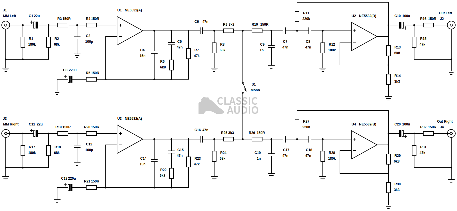
Figure 4. A complete pre-amplifier with mono switch
Figure 4 details a complete phono stage with a much better implementation of the mono switch than the two methods described above; a minimum parts count low cost design intended for an easily manufactured compact surface mount layout, although there is no reason why through hole technology cannot be used. The aforementioned output stability series resistors, R16 and R32, are seen at the far right of the schematic and are acceptably low 150Ω parts that will not exhibit any appreciable insertion loss into a reasonably designed line input. The mono switch, S1, sits right in the middle of the schematic, nested in the subsonic filter and correction pole which compensates for the first stages inability to amplify below unity. Placing the switch inside the subsonic high-pass filter also allows for useful DC decoupling which prevents DC offsets caused by op-amp offset voltages and bias currents from generating clicking transients when the switch is operated. Undemanding 3.3kΩ current sharing resistors, R9 and R25, are used for bridging here which is just low enough to prevent excessive crosstalk across the switch contacts while presenting a sufficiently light load to input amplifiers U1 and U3. R10 and R26 add the additional resistance needed to set the right time constant for the correction pole through capacitors C9 and C19 and also prevent potential shorting of the capacitors when the switch bridges the two channels, which might potentially damage the switch contacts, however unlikely this might be at the low signal voltages present.
The gain is split between the two stages to allow for the RIAA gain stage to make the most use of its open loop gain by applying a higher feedback factor and thus improving distortion performance, with the second stage making up the extra 10dB for a total of 41dB at 1kHz. This has the added benefits of decreasing the signal voltages across capacitors C4 to C9 left channel, and C14 to C19 right channel, by 10dB for the same output level, allowing the use of low cost polyester parts without the risk of appreciable capacitor distortion which is roughly proportional to the square of the AC voltage across them. The author considers a subsonic filter around the 20Hz mark with at least a 3rd order slope, as it is in Figure 4, to be essential for high quality reproduction, mandating a two stage design which presents an excellent window of opportunity for the inclusion of a mono switch. Unfortunately it is not particularly easy to generate component values for this topology, and a good deal of informed trial and error in SPICE simulation starting for ballpark values was necessary to turn Figure 4 into a fully functioning design.
Conclusion
By now it has hopefully been demonstrated that the option for mono summing is a thing very much worth having. Some of the examples provided have been rather extreme in their nature, having been selected specifically for the purposes of demonstration, but the effect will be present to some degree on virtually all discs depending on age and condition. Even brand new mint mono pressings, which seem to be now issued with increasing frequency will see some improvement through channel summing. For very worn or damaged discs, switching to mono may not be enough to make the material listenable and in this situation some sort of high-cut filter is very useful. Sometimes backing the treble control off by a little is usually enough to make things bearable in the case of extreme distortion and wear, as has already been alluded to; a good case for tone controls in general. As a brief passing footnote on the extensive subject of early discs, a well designed bass and treble tone control can also help to equalise pre-RIAA pressings to within a decibel or so when used with a standard RIAA phono stage.
Ultimately, the mono switch is seen less often because latching switches are relatively expensive parts relative to the rest of the components in many phono stages. Coupled with the difficulty of implementation in stand-alone single stage designs intended to bridge the gap between a turntable and a 21st century integrated amplifiers this has sadly left more of this very useful feature in the past than it should be in the authors estimation. Interestingly, the better portion of phono stages that offer pre-RIAA equalisation don't also feature mono switching which would be necessary for the best reproduction of pre-RIAA discs, all of course which would be mono only. Perhaps things will change...
If you have any questions or comments relating to this article, then feel free to contact the author .