
Introduction
There's no doubt that active loudspeakers, particularly of the professional monitoring kind can offer quite excellent value for money when it comes to the high fidelity reproduction of sound and music. A great many would be owners have brought them into careful consideration while weighing up a change of speakers in their component systems, and have unfortunately been put off by their seemingly irredeemable incompatibility of connectivity with the consumer units already in their possession. This is particularly true for integrated amplifiers which feature only line inputs and speaker outputs, failing to provide a consumer line-level pre-amplifier output, let alone a professional level balanced one. These are usually only found on more expensive separate pre-amplifiers, whose cost may be well in excess of the speaker upgrade considered in the first place. Most who consider the active option consequently put the idea aside as impractical, and instead try their luck in the dark world of subjectively assessed, and objectively quite lacking passive consumer loudspeakers. This approach very seldom doesn't produce a slightly dissatisfying outcome that may cause them to wonder whether the time, effort, and money was really worth it after all.
The author writes this article to share his own personal solution to the problem stated, having been met with the challenge of mating a pair of Tannoy Gold 8 studio monitors to a Technics SA-200 receiver of 1979 vintage. The receiver in question, while most aesthetically pleasing is sorely lacking on on its own, as with all integrated amplifiers and receivers, to deliver some sort of appropriate output to work in tandem with the monitors.
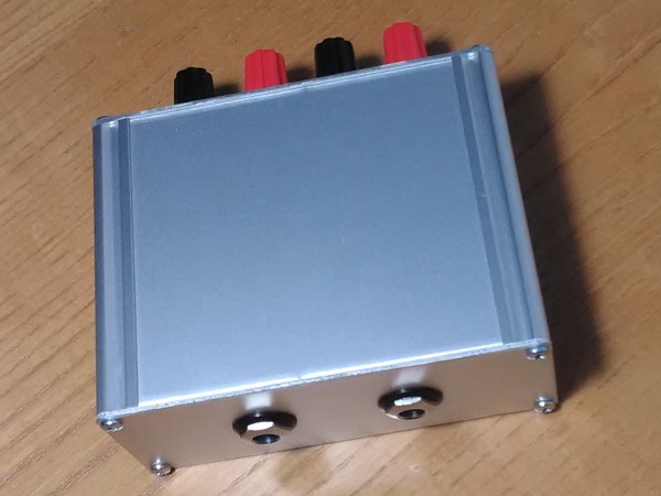
Figure 1. Low cost matching unit for active monitors
In a brief glimpse, the solution to this problem of converting a speaker level output to a professional balanced line-level one takes the form of Figure 1, a small unit of low cost and complexity that can easily be tucked away out of sight and mind. The constructor is then free to enjoy the superbly realistic sound of even some of the lower end offerings in the realm of professional monitoring, without any expensive amplifier or pre-amplifier modifications or upgrades.
The benefits of active speakers
The reader will be aware at this point of firm allusions towards the superiority of professional active monitors in contrast with passive speakers that find themselves more in the contemporary of the consumer HiFi world. At this point it is useful to lay out these advantages, however it must be said that the advantages take themselves in two particular directions. The first being in the difference between active and passive loudspeakers, the second being in the convention of how consumer and professional audio units are designed and marketed. The former direction shall take precedence below.
- Active loudspeakers almost always contain active crossovers, which are similarly almost always far closer to the ideal of what a crossover should be in contrast to their passive counterparts. Higher order crossovers that transfer less energy outside the crossover point, and hence less distortion caused by drivers handling frequencies outside of their optimum ranges, are possible without great expense. Passive loudspeakers usually try to get away with a first order crossover to cut the significant cost of passive crossover components. While workarounds such as polypropylene woofers with their well behaved roll-off characteristics may create acceptable results for the price tag, there will be more overall distortion. The tweeter especially has to cope with almost as much power below the crossover point as above it.
- The crossover is usually placed ahead of the power amplifiers, situated within the active speaker, which eliminates all interaction between the crossover and the loudspeaker driver. This results in a much less coloured sound, particularly at high power where the loudspeaker voice coil will start to heat up, increase its resistance and skew the crossover characteristic, typically peaking the frequency response around the crossover point in an unpleasant subjectively 'shouty' manner.
- As there is no crossover between the power amplifiers and the loudspeaker drivers, each power amplifier will be directly coupled to the loudspeaker drivers, as opposed to through a lossy passive crossover and meters of speaker cable, yielding greater control of the bass driver, greater efficiency, and allowing each power amplifier to be optimised to the specific requirements of each driver.
- If one power amplifier clips, then it will only generate distortion in its respective driver, which will be far less audible than a full-band amplifier driving a passive loudspeaker. High order distortion products generated by mid-bass amplifier clipping will not result in large amounts of energy being sent to the tweeter, potentially damaging it. Furthermore, it is common for each amplifier section to feature a limiter to ensure that it does not clip at all and cannot damage the driver it feeds, a major advantage of longevity for those who like it loud.
- Electronic low end alignments that modify the frequency response of the drive amplifier can be used that dramatically increase bass extension and lower distortion, resulting in a much deeper and cleaner bass response for a given enclosure size, particularly with bass reflex designs.
Having turned our attention away from the benefits of active over passive, let's change our perspective towards the comparison between professional monitors and consumer HiFi speakers. These are best summed up in paragraph form as they have more to do with the wants and needs, although the latter is quite debatable, of both markets.
Professional audio has always been geared towards the objective performance of the equipment put to use in its sphere. By definition, its practitioners know exactly what they are doing with, and what they want out of, the equipment that they purchase. Although these requirements are most informed by an understanding of the human perception of sound, they are almost always not measured by it as a first resort. As a result of this, professional equipment is designed and marketed to have as least noise, distortion, and frequency response deviation as is possible. In most cases a good specification can be relied on to sell the unit, which significantly reduces marketing costs, allowing those savings to be passed on the buyer.
Consumer audio, on the other hand, is designed and marketed to appeal to buyers who may not be familiar with any objective means of measuring performance against perception. Much of the marketing claims that only listening tests are valid. Therefore, listening tests and subjective reviews that stray away from those dull-sounding and seemingly incomprehensible technical specifications are the most consulted means by which a consumer might choose a pair of consumer loudspeakers. Reviews are almost always entirely subjective and manufacturers, particularly when it comes to loudspeakers, lay out a very vague specification, characterising frequency response without even mentioning the measurement thresholds (is it 50Hz to 24kHz at -3dB, -6dB, -10dB or even -12dB?). The author has yet to see a manufacturer publish anything close to a remotely useful frequency response plot.
It is well known that a loudspeaker that is proclaimed to sound, or sounds to the buyer, as 'exciting' or 'expressive' or any other usefully muddy and ill defined quality, may deviate quite dramatically in terms of acoustic accuracy from one that sounds 'dull' or 'too restrained'. Once the buyer of said loudspeaker brings it home, without a salesperson present to highlight these glittering attributes and starts listening to their music in their listening room, the same loudspeaker may sound obtrusive and will quickly fatigue the listener with these previously dazzling qualities. Upon this revelation many buyers will be reluctant to return the product that they themselves picked out and will do their best to live with the situation.
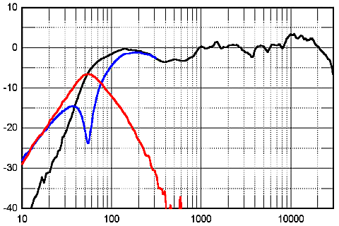
Figure 2. A rather uneven plot of dB vs. Hz for a subjectively accoladed speaker
Figure 2 shows the frequency response of a consumer loudspeaker that gained much admiration and positive review from the point of its release from the undeservedly trusted HiFi press. The response was of course not measured and published by the manufacturer. It's frequency response that is representative of most well-reviewed consumer loudspeakers around the several hundred pound mark. Starting from the bottom end, the reflex port output peaks 3dB or so below where it should around 55Hz for 'tight' bass and possibly also to make any room defects around this point less audible. Moving up to 140Hz we have a broad peak for 'punch and drive' and possibly a little 'authority in the low end'. This then falls down in the 400Hz to 700Hz range so the speaker won't sound 'boxy' to the reviewer. Moving up to 1kHz, the level is back up again for 'midrange clarity', but drops 3db in the 2kHz to 4kHz region to prevent 'harshness', before rising up another 3dB above 10kHz for a 'sparkling' high end. All of these attributes, it goes without saying, are intentional defects to fidelity, but give a subjectively exciting sound that will impress the reviewer enough to give it a full five stars and a product of the year award. Taking out advertising in the glossy vessel of said review in months previous goes a long way also...
Professional active speakers, on the other hand, are not deliberately marred in the design stage in the manner mentioned in the previous paragraph. The goal is to get the frequency response as flat as possible, and to do it at a price that will make it worth it for the buyer to go out of their way to obtain it. Very little is spent in marketing and greasing the palms of various unscrupulous gatekeepers in acquisition of positive subjective reviews. What subjective reviews there are most often take the form of confirmation of the objective performance and are made by those most qualified to do so; professional sound engineers, producers and artists.
Many patrons of consumer style loudspeakers will remonstrate against professional monitors as being 'clinical', 'analytical' or 'revealing of flaws'. However, it is the opinion of the author that high fidelity audio should be taken literally, with accurate reproduction of sound and therefore realism taking priority over preferential mangling which can be done by more dynamic and variable means such as equalisation.
Active speaker input requirements
Drifting back to the practicalities of active speakers with a view of connecting them to some source, it is a good idea to look at exactly what sort of input they require to work at their best. A balanced one will certainly be the most likely, if not the only one likely, to avoid problems with hum and noise pickup, as the speakers will be placed at some distance from the source and will probably derive mains power from a different set of sockets from the rest of the source equipment. A large ground loop will come with the territory, and cannot be avoided unless the listener prefers to have their speakers situated on the HiFi rack, one on top of another. For this reason all decent monitors will feature balanced inputs, through either TRS or XLR connectors, and unbalanced ones will be conspicuously absent as a warning of their futility.
To obtain maximum SPL, most monitors will need an input voltage of +4dBU or 1.228V RMS, although the sensitivity will usually be variable by a potentiometer control somewhere. This 1.228V RMS should come from a reasonably low source impedance, less than or equal to 600Ω, and be delivered into an input impedance of 10kΩ upwards. The level should not exceed ±12V peak, even though this will be well past maximum level by a factor of 10, so as to protect the op-amp inputs on the monitors balanced receiver that will be running off a minimum of ±12V, although much more commonly ±15V. It is never a good idea to assume that input clamping will always be present.
Integrated amplifier outputs
Integrated amplifiers are quite simple animals, they often contain no other active stage than the power amplifier itself. In a custom that continues today, the inputs are switched onto an attenuating potentiometer, functioning as the volume control, that feeds into the power amplifier stage input. The power amplifier is designed with enough gain so that a reasonably strong source such as a CD player can take it up to its maximum level without any pre-amplification. Sometimes a balance control is incorporated onto the output of the volume control potentiometer, attenuating one channel to a greater degree than another depending on its position. Often a tone control is put into the power amplifiers feedback network. Many features are therefore realised without deploying more than the bare minimum of a singular amplifying stage. This is the case for all 20th century integrated amplifiers that the author has come across, and although the author has found some units with complicated pre-amplifier circuitry in the wild, they are more the exception than the rule.
A limitation of the simplicity of the classic integrated amplifier topology is that there is no output other than the power amplifier output, it being the only active stage. A headphone output is added in a lot of cases, but this is only the output of the power amplifier connected through a 330Ω current limiting resistor in most cases. We must therefore work with the power amplifier output and derive from it the necessary level required by the active monitors.
For the sake of example, consider an integrated amplifier of modest output power; 25W into an 8Ω load which delivers a peak output voltage of 20V. The RMS output voltage will be 14.14V at maximum power, and output current available is high at over 3A peak into the specified 8Ω load, but it need not deliver this current as part of its operation. The amplifier doesn't need to see an 8Ω at its output to function correctly, although its a different story for some esoteric amplifiers such as valve amplifiers which may find themselves inclined to self destruct under such circumstances. In fact, if the loading is lighter than the rated load, the distortion performance of the power amplifier will improve somewhat. Output impedance will be well under 1Ω.
The vast majority of conventional solid state integrated amplifiers will have an output that it referenced to ground. The negative speaker terminal will be connected to the amplifiers internal ground and this can be quickly checked for by measuring continuity between the negative speaker output terminal and the shell of an RCA input connector. If this is not the case, then the amplifier probably uses a BTL arrangement, and it is not wise to even attempt to match it to any external source other than a speaker. Fortunately this topology has not gained much ground in conventional integrated amplifiers, mainly because it requires two amplifiers and an inverting stage per channel, and is most often found in cheap class-D amplifiers.
Matching circuit
Having considered the input requirements of active monitors; 1.228V RMS, with the offerings available from the outputs of integrated amplifiers; 17.68V RMS, it becomes apparent that only passive attenuation and some type balanced matching is required to effect a marriage of convenience. If there is no attenuation, there will be far too much noise picked up from the power amplifier and the very real risk of overloading the monitor input to the tune of permanent damage. The attenuation is easy enough, a pair of resistors can be put into service to give the 15dB or so of attenuation to put the level into the right ball-park with a good margin of headroom. As there is only one output referenced to ground, the balanced part seems elusive without the use of an expensive, magnetic hum gathering, low frequency distorting, and altogether less than ideal audio transformer.
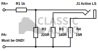
Figure 3. Monitor matching schematic (one channel shown)
The solution to this conundrum is shown in Figure 3, a very uncomplicated arrangement consisting of a grand total of 4 resistors per channel. Starting with the obvious, the input from the integrated amplifier, PA+, is first put across a common or garden L-pad attenuator made up of resistors R1 and R2, attenuating the amplifier output by the 15dB needed to make the level friendly to the monitor. This is then connected to the hot tip pin of TRS connector J1 which will be connected to the monitor. Next up is R3, which is connected from the power amplifier ground reference, PA-, to the cold ring pin of J1. Finally R4 is connected from the amplifier ground to the ground sleeve pin of J1.
Although it does not seem to be so, this is in fact a balanced output, because the impedances on the hot and cold outputs are of equal impedance. With R1 and R2 in parallel, as the power amplifier output is of low impedance, the impedance on the hot output pin will be 180Ω with reference to power amplifier ground - exactly the same as the cold pin through R3. As the impedance is balanced, any hum, noise or other electrical excreta that may couple onto the line to the monitor will be equal on the hot and cold inputs and therefore be rejected by the balanced receiver. It does not matter that there is no signal on the cold pin as the balanced receiver will measure the difference between them and reject common mode noise regardless as to whether the signal itself is fully differential. This technique is known as impedance balancing and is often used to generate a operable balanced output without going to the trouble of generating a fully differential signal.
The function of R4 might seem obscure, but it performs a couple of much needed roles to complete the circuit. First of all, it presents just enough resistance in the line of the ground path to impede any ground loop currents that might be flowing on the power amplifier ground line to the point where they cannot induce a significant enough voltage in the parasitic resistance of the ground path to cause trouble on the unbalanced side of the circuit. The balanced receiver in the monitor will not be able to reject any hum induced ahead of its cold reference via R2 and R3, so this must be minimised. Secondly, if speaker terminals are connected the wrong way round by accident, then the amplifier output will not see a short to ground via the ground connection on the monitors input. Such a short could damage the power amplifier, if it has no output short circuit protection, the monitors input via over-current, or both. With R4, if the speaker terminals are connected the wrong way around all that happens is R4 blows, before which time the user should be able to notice something is amiss if the other speaker is wired the correct way around.
With the matching circuitry connected in place of a passive loudspeaker, the input impedance presented to the power amplifier at 1.22kΩ is a great deal higher than the nominal 8Ω that it would see from a loudspeaker. Although it might be tempting to add some parallel resistance of 10Ω or so across the unit so as to make it better simulate the load that the power amplifier was designed for, there really is no need to do this. As already mentioned, solid state amplifiers don't care what the load impedance is, so long as it does not cause overload, and a very light loading of 1.22kΩ will not cause any ill-effects. As the current required by the load will be much lower, output stage distortion will be much reduced. The 10Ω of parallel resistance might be required to make some valve amplifiers behave themselves, particularly in regards to severe arcing across the output transformer with some zero feedback pentode output designs, but this is a very costly and inefficient method of driving active speakers indeed.
A final word of warning must be offered against using the matching circuit of Figure 3 with BTL amplifiers. Doing so may result in damage to both the amplifier and the monitor input. As previously mentioned, it is easy to check for this by ensuring continuity between the negative speaker terminal and the outer shell of an RCA connector.
Construction notes
As the matching circuitry is very simple, a basic point-to-point construction style can be employed to yield a quick and solid build within the course of an hour. Any enclosure can be used as there are no high impedance points in the circuit that are particularly susceptible to hum and noise pickup. In this case the circuit was built inside an extruded aluminium Lincoln Binns U-Case enclosure of the smallest variety, but an ABS enclosure will offer no disadvantage. Uncommonly, the metal enclosure itself was not referenced to any ground point in the matching circuit; in confidence of the low vulnerability to noise pickup.
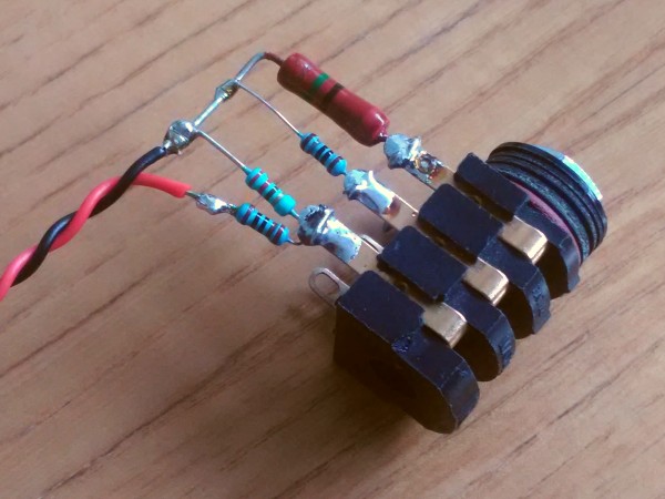
Figure 4. Wiring the resistor network point-to-point directly onto the TRS connector
Figure 4 demonstrates just how simple the point to point construction can be, with all the the resistors soldered directly onto the TRS connector. An XLR connector could also be used, but the author did not have any to hand during the short duration of the build - being in possession of an excess of TRS connectors. Using a TRS connector such as the one shown makes the construction very easy. The large resistor on the right, R4, was chosen from an antique collection residing at the bottom of a neglected pile of obsolete components as its physical size and thicker leads were more conducive to a solid construction. R4 is the least critical part of the build, so it need not be the epitome of the latest-and-greatest of resistors.
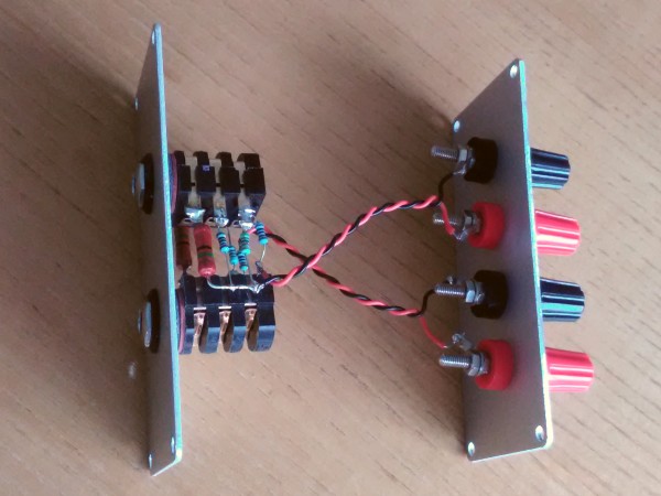
Figure 5. Completed unit with sides removed to show wiring
With both channel shown in Figure 5, the completed unit is presented. As to be expected, there's not very much to see but the screw on speaker input terminals and the twisted pair wiring to the matching networks and TRS connectors. The wiring is twisted mainly to make the construction easier, with less risk of flexing and breaking resistor leads during fitting and also for the purely aesthetic element. There is practically no risk of crosstalk within the unit due to the very low impedances on the speaker inputs. The TRS connectors are insulated types and do not have any electrical connection to the chassis. Only one matching network is visible, the second channels resistor network is concealed under the lower TRS connector.
When it comes to wiring the completed unit into a system, it is better to prioritise making the unbalanced side of the wiring shorter, so the unit is best put in close proximity, with correspondingly short wiring, to the power amplifier. As the current demand of the circuit on the power amplifier is very low, inexpensive light gauge 'bell wire' type cable can be used without consequence.
Conclusion
As far as the author is aware, there is no description of any matching circuit available elsewhere that describes how to successfully use active monitors with a conventional HiFi set-up. This seems most troubling as the author strongly feels that professional monitors really are a quite excellent way of enjoying music.
It is unfortunate that so far, judging by comments on internet forums, that many people have been deterred from using active speakers with classic amplifiers. Hopefully the content in this article will demonstrate that it is not necessary to give up hope and return to the grim subjectively foggy world of consumer audio in such a situation. With a little bit of soldering, some simple passive circuitry, and a handful of cheap parts, those seemingly unobtainable advantages are just around the corner.